Controlling the MultiWii

In my last post I had explored ways to accessing sensor data from the MultiWii.    I’ve managed use the same serial method to get some of data to the PI, However  I’m having problems using the UART specifically shifting the power levels from the MultiWii to the PI.

I changed my focus onto controlling the MultiWii’s flight through the RC input channels. I did look into controlling this through serial, however it would mean I would lose my own control of the quadcopter through my RC receiver which I want as a fail safe.

Furthermore I tried controlling PWM using the PI’s GPIO, however the values move around too much and from what I’ve read there is only a few pins that support PWM on the PI and limited support at that.

So instead I’m taking a different approach using another Adrunio board and taking the PWM input from the receiver and outputting it back out. Then I implemented a basic serial protocol to set the Throttle, Pitch, Yaw and Roll values manually. This will allow the PI to control the quadcopter and if anything goes wrong for myself to flip a switch to take over via RC.

I have also attached a Ultrasonic distance sensor to the Ardunio to give out the distance from the ground  in order to be able balance the Throttle later down the line.

Basic Wiring Diagram

The serial protocol I wrote is a very basic, it takes 5 byte packet containing two start bits and then a  command, value and finally a end bit. Which look like ‘%^T0;’ in a string.

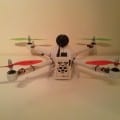
The Uno is too big to fit inside the quadcopter so I will be converting this to a Mini Pro in the future.

So Far….

This blog represents the work of my computer science dissertation project aimed at successfully attaching a Raspberry PI onto a quadrocopter and adding autonomous behaviour which could be used for various applications such as search and rescue and 3D building construction.

The Quadcopter

So far I have explored ways of interfacing the control board (MultiWii) and have found two possible methods.

I2C – A two wire interface that can be used to directly access the on-board sensors and motors through memory addresses. The Raspberry Pi actively supports this through its GPIO pins. My attempts at getting to this work has be partially successful, in the since I’ve managed to access data. However there is very little documentation on the memory address for the MultiWii which has caused problems using it.

Serial – The MultiWii board has two serial ports one UART and a FTDI, these can be used to interface with the PI through the GPIO and in my experiments I found the PI will happily power the MultiWii board without a problem.

Using the FTDI (USB connection) from the PI appeared to be a problem, however there is drivers for it. But my attempts resulted in compile errors and FTDI causing the system to crash.  Using the GPIO is feasible however at this time I was trying to avoid directly connecting the two boards. So I turned to using a normal computer to make a proof of concept to ensure it worked before I committed to spending a lot of time messing around

I wrote a c# wrapper that encapsulates the MultiWii protocol and can grab most of the sensor data allowing. This worked so well that I’m considering using it as a ground station and passing the serial data over a network connection from the PI for monitoring purposes.

C# MultiWii Ground Station prototype


From this I have now started working on a version for the PI, I first started with c++ however due to the lack of fully functional IDE’s and the compile time, I’ve decided to give it a try with python that is completely supported and heavily used on the PI.

Additionally I’ve attached a USB camera to the PI my attempts at streaming this camera over the network were unsuccessful as the framerate was too slow for anything useful. However I found more success by grabbing frames from the camera and saving to a file. Which using Lighttpd I was able to view remotely. This was much faster!

I’ll keep this blog updated as this project progresses, Questions and feedback are most welcome.